



Seven Verified Components
Every component and part number matches Titan’s official PowrCoat bleed-valve parts table.
Controlled Pressure Relief
The valve opens the return path for priming, flushing, shutdown, and service procedures.
Tungsten Sealing Pair
Titan 761-715 ball works against Titan 944-904 valve seat to close the return path.
All Product Links Verified
Each product destination opens as a live AllTitanParts page for the exact component.
Assembly Overview
The PowrCoat 730 bleed valve is a manually operated return-flow and pressure-relief assembly connected to the high-pressure fluid system. Opening the valve allows coating and trapped air to move through the bleed or return path during priming, flushing, and pressure release. Closing the valve directs pressurized material toward the spray hose and gun.
| Position | Titan part number | Official description | Service role |
|---|---|---|---|
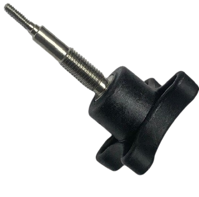
| 1 | 944-024 | Knob | Provides the manual control used to open and close the bleed valve during priming, flushing, pressure relief, and normal spray setup. |
| 2 | 944-020 | Valve Housing | Forms the structural body of the valve and aligns the seal, stop, ball, gasket, and seat inside the return-flow path. |
| 3 | 944-004 | PTFE O-Ring | Provides the documented sealing position in the valve housing to reduce fluid leakage around the moving valve components. |
| 4 | 944-026 | Valve Stem Stop | Limits the designed travel of the operating mechanism so the internal parts open and close within the intended range. |
| 5 | 761-715 | 1/4-Inch Tungsten Ball | Works against the valve seat as the primary hard sealing element controlling coating flow through the bleed path. |
| 6 | 945-003 | Copper Gasket | Seals the documented interface behind the ball-and-seat position and supports pressure containment in the valve body. |
| 7 | 944-904 | Tungsten Valve Seat | Provides the wear-resistant seating surface for the tungsten ball when the return path is closed. |
Functions Supported by the Assembly
Priming Return Flow
Allows coating and trapped air to circulate through the return path while the pump is primed.
Flushing and Cleanup
Provides a controlled route for flushing material and solvent from the fluid system.
Pressure Relief
Supports safe depressurization of the hose, filter, valve, and connected fluid circuit before service.
Normal Spray Shutoff
Closes the return circuit so pressurized coating is directed toward the hose and spray gun.
Service Applications
Use this diagram when material continues through the bleed hose with the valve closed, the pump cycles with the gun shut off, the valve will not operate smoothly, coating leaks around the housing or seat, or a knob, seal, stop, ball, gasket, seat, or housing is visibly damaged.
High-Value Replacement Parts
All seven product cards below correspond directly to the numbered Titan bleed-valve diagram and use verified live internal URLs.
Titan 944-024 Knob
Provides the manual control used to open and close the bleed valve during priming, flushing, pressure relief, and normal spray setup.
Titan 944-020 Valve Housing
Forms the structural body of the valve and aligns the seal, stop, ball, gasket, and seat inside the return-flow path.
Titan 944-004 PTFE O-Ring
Provides the documented sealing position in the valve housing to reduce fluid leakage around the moving valve components.
Titan 944-026 Valve Stem Stop
Limits the designed travel of the operating mechanism so the internal parts open and close within the intended range.
Titan 761-715 1/4-Inch Tungsten Ball
Works against the valve seat as the primary hard sealing element controlling coating flow through the bleed path.
Titan 945-003 Copper Gasket
Seals the documented interface behind the ball-and-seat position and supports pressure containment in the valve body.
Titan 944-904 Tungsten Valve Seat
Provides the wear-resistant seating surface for the tungsten ball when the return path is closed.
Buying Guide
1. Confirm Assembly 944-028A
Use the PowrCoat bleed-valve diagram connected to the model’s high-pressure fluid system.
2. Identify the Failure Type
Separate control, housing, travel, external sealing, and internal shutoff problems.
3. Match Positions 1–7
Confirm the numbered callout and every digit of the Titan part number.
4. Inspect Mating Components
Check the ball, seat, gasket, O-ring, housing, stop, and knob as one operating system.
Maintenance
Operate the valve through its full range during priming and cleanup, flush the return path with a coating-compatible solvent, inspect for continued bleed-hose flow after closure, and keep the knob, housing, threads, ball, and seat free of hardened coating. Never service the valve until the complete fluid-pressure relief procedure has been completed.
Repair Planning
For control or movement faults, inspect the 944-024 knob, 944-026 stop, 944-020 housing, operating threads, residue, and valve travel together. For sealing faults, inspect the 944-004 O-ring, 761-715 ball, 945-003 gasket, 944-904 seat, housing interface, and return hose before building the order.
Fast Navigation
PowrCoat 730 Bleed Valve FAQs
What type of page is this?
It is an exploded-parts-diagram category for the Titan bleed valve assembly used on the PowrCoat 730.
Which complete bleed valve assembly is shown on the PowrCoat 730?
Titan identifies the complete bleed valve assembly as 944-028A in the PowrCoat main and wall-mount parts lists.
How many internal components are shown?
Titan’s bleed-valve parts table lists seven positions.
Which part is the operating knob?
Titan 944-024 is position 1 and provides the manual control for opening and closing the valve.
Which part is the valve body?
Titan 944-020 is position 2 and forms the housing that aligns the internal valve components.
Which seal is shown inside the valve?
Titan 944-004 is the position-3 O-ring.
Which component limits operating travel?
Titan 944-026 is the position-4 valve stop.
Which parts form the hard sealing pair?
Titan 761-715 ball and Titan 944-904 valve seat form the documented ball-and-seat pair.
Which gasket is used at the seat interface?
Titan 945-003 is the position-6 gasket.
What should be checked when fluid continues through the bleed hose?
Inspect valve closure, contamination, the tungsten ball, valve seat, gasket, housing, and return path before replacing components.
Why should the complete pressure-relief procedure be followed?
Turning off compressed air does not automatically remove trapped fluid pressure from the gun, hose, filter, or valve system.
How should parts be ordered accurately?
Match the diagram position, exact Titan part number, and the observed failure point, then inspect mating components before ordering.
Match the Bleed Valve Component Before Ordering
Identify the operating or sealing fault, compare the official diagram position, and verify the exact Titan part number before replacing any component.
- Exact Titan part number
- Bleed valve diagram position 1–7
- Complete assembly 944-028A
- Leak, travel, control, or shutoff symptom