
The PowrBeast 4700/4700T has two bleed valve diagrams. The standard one is built around the 944-009 housing, 944-011 stem, 0294499 seal and 9841502 outlet valve ball. The heavy materials one uses the 945-600A bleed valve with a 945-906 tungsten valve seat and 138-226 carbide bearing ball. Match the picture to your valve, or call to confirm.
What the bleed valve is for
The bleed valve is part of how you relieve pressure on a sprayer that works at up to 3300 psi. Where it sits in the sequence and how far to open it are in the pressure relief procedure in your PowrBeast manual, which we do not paraphrase here because the order of steps matters. What matters for parts is that this valve is opened and closed often and holds back full system pressure while you spray. Its seals and seat take the wear.
The standard assembly
The standard assembly is on the PowrBeast 4700/4700T Bleed Valve Assembly page, with 13 parts. The same assembly, with the same numbers, also appears on the bleed valve pages for the other PowrBeast models. These are the parts you will most likely need:
Standard bleed valve assembly
The rest of the page is hardware: a hex screw (944-047), a flat washer (944-029), a spring washer (9820905), a spacer (0295731) and an inverted retaining ring (9822516). Order them by callout if you are rebuilding the valve.
The heavy materials assembly
The second diagram is the PowrBeast 4700/4700T Bleed Valve Assembly, heavy materials page. It lists 15 parts and it is a different design, with its own numbers throughout. It also includes the plumbing that carries the bled fluid away: a bleed hose and the tube, tee and elbow around the valve.
Heavy materials bleed valve
The two PTFE O-rings, 891-183 and 891-073, plus the knob (945-005) and locknut (970-011) complete the valve itself. Note that the housing, stem and knob numbers all differ from the standard assembly. A 944 number does not fit a 945 valve.
Which diagram applies
Both pages are titled for the 4700 and the 4700T, so the title cannot settle it. We do not say which assembly is fitted to which unit, because the diagrams do not say. Match the picture to the valve on your machine: the heavy materials page has a hose and tubing run around the valve, and the standard page does not.
- Open both pages in separate tabs.
- Compare the picture with your valve, then check the callout number of the part that has failed.
- Match the part number on your old part with the diagram.
- If you cannot tell, call (713) 931-0006 with your model and serial number and a description or photo of the valve.
Spotting a worn valve
A bleed valve that no longer seals lets fluid escape when it should be closed. You may see pressure that will not hold, or fluid leaking at the valve. As with any ball-and-seat valve, the seat and ball are the first suspects, so on the heavy materials assembly start with 945-906 and 138-226 and the O-rings, and on the standard assembly start with the ball (9841502), the valve seal (0294499) and the seat retainer. Replace a ball and its seat together.
Pressure loss does not always come from here. A worn tip, a clogged filter or pump valves can look the same, and those are cheaper to rule out first. Titan does not publish a service life for any PowrBeast bleed valve part, so replace on symptoms and not on a schedule.
A related assembly on the filter page
The high pressure filter page lists a 944-030A Bleed Valve Assembly at callout 10, next to the filter body and cap. The 944 prefix matches the standard bleed valve parts. That page is the place to look if the bleed valve you need is the one mounted on the filter.
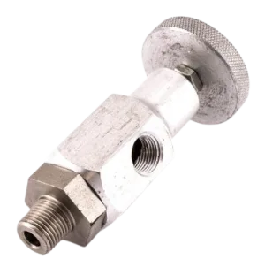
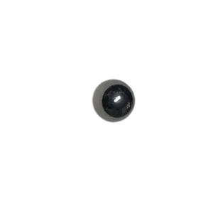
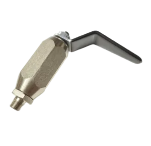
Bleed valve parts from both assemblies:
The Short Version
Two assemblies, two number families: 944 and 98 numbers for the standard valve, 945 numbers and the 138-226 ball for the heavy materials one. Match the picture first, replace seat and ball together, and relieve pressure before you touch anything.
Not sure which bleed valve you have?
Call (713) 931-0006 with your model and serial number and our parts team will confirm the part before you order.
(713) 931-0006Order by Parts Diagram