











Verified Diagram Scope
Part numbers and names are restricted to the current category and Titan Commander documentation.
Diagnosis Before Replacement
Every recommendation begins with inspection of genuine assembly components.
Six-Card Maximum
The commercial section contains no more than six verified component cards.
Verified Commander Links
Navigation uses confirmed machine-family and assembly-category destinations only.
Assembly Overview
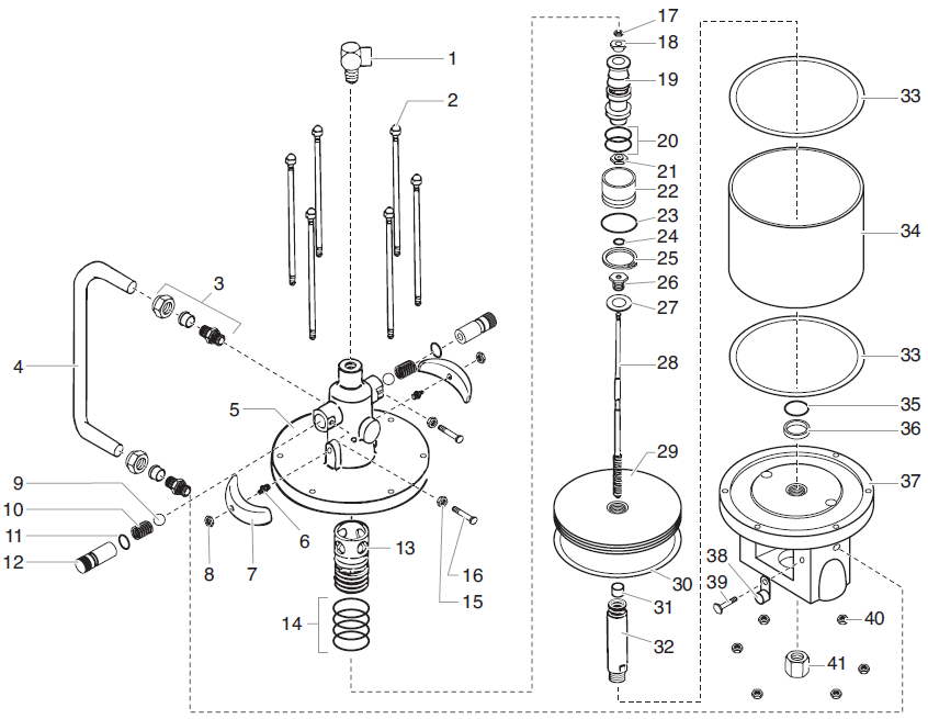
This diagram covers the shared internal components of Commander air motors 742-555 and 742-557. Titan documents the head, trip-valve system, piston, cylinder, valve rod, motor base, seals and coupling hardware used to convert compressed air into reciprocating pump motion.
Verified component index: 742-997, 742-913, 740-925, 743-011, 850-917, 850-952
Functions Supported by the Assembly
Primary Assembly Function
Head, cylinder performs a central function within this documented Commander system.
Pressure or Flow Support
Sleeve, valve supports controlled pneumatic, fluid or structural operation.
Sealing and Retention
Valve contributes to sealing, alignment, filtration, retention or stability.
Service Identification
The exploded page separates genuine service components from adjacent Commander systems.
Service Applications
Use this page for model identification, preventive inspection, targeted repair, assembly rebuilding, pressure or flow diagnosis and purchasing for Commander equipment that specifically uses this assembly.
High-Value Replacement Parts
Only components confirmed in the current Commander diagram or parts table are shown.
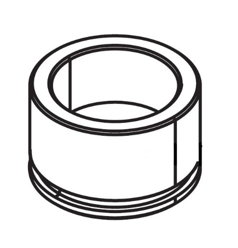
Titan 742-997 Head, cylinder
Confirmed in the current Commander exploded diagram or parts table. Match the item callout and installed assembly before replacement.
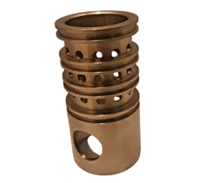
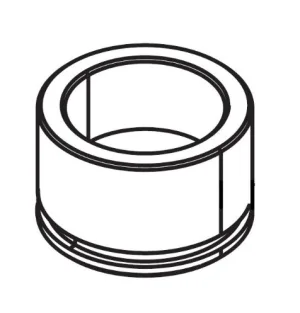
Titan 742-913 Sleeve, valve
Confirmed in the current Commander exploded diagram or parts table. Match the item callout and installed assembly before replacement.
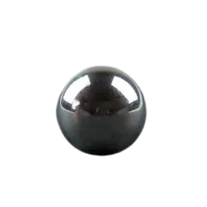
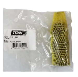
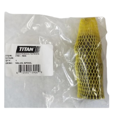
Titan 740-925 Valve
Confirmed in the current Commander exploded diagram or parts table. Match the item callout and installed assembly before replacement.
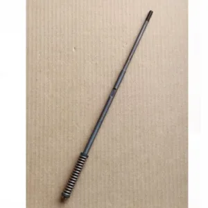
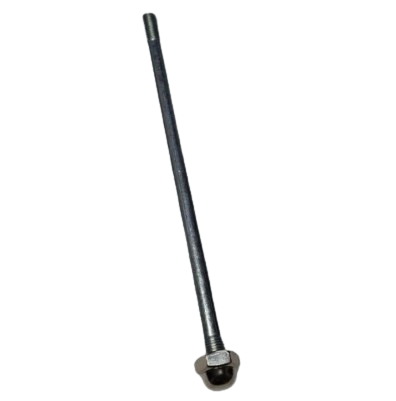
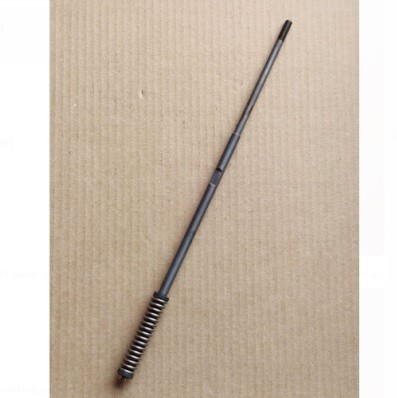
Titan 743-011 Valve rod assembly
Confirmed in the current Commander exploded diagram or parts table. Match the item callout and installed assembly before replacement.
Titan 850-917 Piston
Confirmed in the current Commander exploded diagram or parts table. Match the item callout and installed assembly before replacement.
Titan 850-952 Cylinder
Confirmed in the current Commander exploded diagram or parts table. Match the item callout and installed assembly before replacement.
Buying Guide
1. Confirm the machine
Record the complete Commander model and mounting configuration.
2. Confirm the assembly
Match the assembly title, item callout and part number.
3. Diagnose the symptom
Inspect connected air, fluid, filter, bleed and mounting systems.
4. Check availability
Do not assume an older documented part remains available or interchangeable.
Maintenance
Relieve pressure before service, inspect grounded high-pressure hoses, keep the assigned filter clean, maintain moisture-free air, use compatible cleaning materials and document recurring wear.
Repair Planning
Record the Commander model, ratio, mounting style, assembly number, item number, part number and symptom. Inspect neighboring components and determine whether individual service parts or a complete assembly best addresses the confirmed fault.
Fast Navigation
Extensive FAQ
What type of page is Commander 742-555 and 742-557 Air Motor Parts?
It is a exploded air-motor assembly parts page for the SPEEFLO Commander family.
Which parts are confirmed on the Commander 742-555 and 742-557 Air Motor Parts page?
Confirmed examples include 742-997 Head, cylinder, 742-913 Sleeve, valve, 740-925 Valve, 743-011 Valve rod assembly.
Why must the complete Commander model be checked?
Commander equipment uses different motors, pumps, mounts, filters and accessories. Match the complete model and assembly number.
What should be inspected before replacing parts?
Relieve pressure and inspect air line 742-943, trip springs 738-213, valve sleeve 742-913 before deciding that replacement is necessary.
Can similar Commander parts be interchanged?
Do not assume interchangeability. Confirm the exact documented part number, connection size, pressure rating and assembly.
What causes unstable operation?
Air leakage, restricted material flow, packing wear, valve contamination, filter blockage or loose mounting can produce unstable operation.
How should pressure loss be diagnosed?
Check air delivery, material pickup, the fluid section, outlet filtration and the pressure-relief path before replacing a component.
When should seals or packings be replaced?
Replace them after inspection confirms leakage, bypass, swelling, hardening, scoring damage or loss of sealing performance.
What maintenance reduces downtime?
Flush compatible material, inspect hoses, keep filters clean, maintain moisture-free air and record recurring wear.
How were internal links selected?
Only verified Commander machine-family and assembly-category destinations related to this page are included.
What information belongs on a repair order?
Record the complete model, mounting style, pressure ratio, assembly number, item number, part number and operating symptom.
Why diagnose before replacement?
Connected air, fluid, filter, bleed and mounting systems can create similar symptoms. Diagnosis avoids replacing a sound component.
Identify the Correct Commander Part Before Ordering
Use the machine, assembly diagram and operating symptom together to reduce mismatched orders.
- Complete Commander model number
- Assembly and item number
- Titan part number
- Operating symptom or component name