
Park the slider and piston at the bottom of their stroke, stop the engine and relieve pressure. Unbolt and lower the fluid section, unhook the piston rod, then remove four socket screws with a 1/4 inch hex wrench and slide the pump housing off the gear housing. Pull the crankshaft, output gear and slider, clean and inspect them, replace worn parts with their thrust washers, regrease with Lubriplate GR-132 and 1242 and torque it all back together.
- When the PowrLiner 2850 Gears or Slider Need Attention
- Gear, Slider and Housing Parts and Tools
- Stop the Engine and Relieve Pressure First
- Replacing the PowrLiner 2850 Gears and Slider: Step by Step
- Test the PowrLiner 2850 After Replacing the Gears and Slider
- Mistakes to Avoid in the Gear Box
- Order the PowrLiner 2850 Gear and Slider Parts
In the drive end of a PowrLiner 2850, the drive shaft pinion meshes with an output gear, the crankshaft carries its own gear and a pin that runs in the connecting rod bearing, and the connecting rod pivots in the slider, which holds the top of the piston rod in its T-slot. Section 7.4 of Titan's 2850 manual reaches all of it by separating the pump housing from the gear housing, in 34 numbered steps that this guide groups into eight.
When the PowrLiner 2850 Gears or Slider Need Attention
Wear the manual tells you to look for
The 2850 manual gives no running symptom for the gear train, and its troubleshooting table does not mention the gears or the slider. What it does give is a set of inspection limits to apply once the housing is open:
PowrLiner 2850 gear box: what to replace
| Part | Replace when | Notes from the manual |
|---|---|---|
| Crankshaft or output gear | Excessive wear or damage | Replace the matching thrust washers with either part |
| Slider assembly | Scored, or the connecting rod joint moves other than by pivoting, or the connecting rod bearing shows wear | Needs the fluid section off |
| Slider bushing | Scored or out of round | The fix is a new pump housing |
| Drive shaft pinion | Worn or damaged | Replaced through the clutch procedure, section 7.5 |
| Housing gasket | Damaged | Clean it either way |
| Gear housing grease | Metal particles or shavings, when any gear is worn | Remove it and refill with fresh Lubriplate GR-132 |
Rule out the simpler causes first
If the engine runs but the pump will not, the manual's table starts with the pressure knob (clockwise supplies power to the unit), then wiring and an empty tank. The power switch guide covers the switch side. The 2850 is also clutch-driven, and section 7.5 services the clutch separately, including a gap check with feeler gauges. Our article on PowrLiner drive types explains what a clutch drive means for wear and spares.
Gear, Slider and Housing Parts and Tools
PowrLiner 2850 drive parts in this job
The manual fits two thrust washers on the output gear and two on the crankshaft, one of them cylindrical. The 2850 drive diagram lists the 700-688 at callout 16, the 700-514 at 18 and the 700-680 at 21, so match each washer you remove to its callout before you order.
Tools and supplies
- Phillips screwdriver for the four front cover screws
- 3/8 inch hex wrench for the two socket screws that hold the fluid section
- 1/4 inch hex wrench for the four socket screws between the pump housing and gear housing
- A torque wrench in inch-pounds for the manual's two torque values
- Lubriplate GR-132 and Lubriplate 1242 greases, plus oil
- Cleaning supplies for the parts you will reuse
Stop the Engine and Relieve Pressure First
The engine runs with the front cover off at the start of this job, because it walks the slider down to the bottom of its stroke; keep fingers and tools away from the slider and connecting rod while they move. Then switch off and complete the 2850's pressure relief procedure (section 4.5), which bleeds the hose through the gun with the relief valve on PRIME. Our pressure relief article walks through it. Let the muffler cool before you work around it.
Replacing the PowrLiner 2850 Gears and Slider: Step by Step
Step 1: Park the slider at the bottom
Take off the front cover (four Phillips screws). Start the engine, turn the pressure knob clockwise to maximum and toggle the ON/OFF switch in short bursts until the slider assembly and piston stop in their lowest position.
Step 2: Shut down and relieve pressure
Turn the engine off and run the pressure relief procedure. If you are replacing the slider, the manual notes that the fluid section must come off the pump housing, which the next step does.
Step 3: Free the fluid section from the slider
Remove the two socket screws holding the fluid section with the 3/8 inch hex wrench. Lower the fluid section housing about 1/2 inch to clear the transducer, then slide it forward with the piston rod until the rod leaves the T-slot.
Step 4: Split the housings
Take out the four socket screws between the pump housing and gear housing with the 1/4 inch hex wrench and slide the pump housing away. Remove and clean the housing gasket, and replace it if damaged.
Step 5: Pull, clean and inspect the gears
Slide the crankshaft and its two thrust washers out from the gear housing side of the pump housing, then remove the output gear with its two thrust washers. Clean them thoroughly, inspect them and the pinion on the drive shaft against the table above, and replace any grease that shows metal.
Step 6: Remove and check the slider
Slide the slider assembly up and out of the slider bushing at the front of the pump housing. Check the slider, the connecting rod joint and bearing, and the bushing, then clean every part you will reuse, including the crankshaft pin the bearing rides on.
Step 7: Grease and refit the gears
Grease the output gear and its thrust washers, fit the washers on their shaft and insert the gear, gear end first, so its teeth mate with the pinion. Slip the flat end of the greased cylindrical thrust washer behind the output gear, lined up with the crankshaft bore, slide the greased crankshaft through it and turn the crankshaft pin to the bottom (bottom dead center), then fit the greased large thrust washer and lay the gasket over the dowel pins.
Step 8: Refit the slider and close up
Lubricate and fit the slider into its bushing, then slide the pump housing onto the dowel pins until it meets the gasket with no gap, guiding the crankshaft pin into the connecting rod bearing. Torque the four socket screws in a crossing pattern to 200 to 230 in.-lbs, hook the piston rod into the T-slot, push the fluid section up and torque its two screws alternately to 400 to 440 in.-lbs, then refit the front cover.
Which lubricant goes where (section 7.4)
| Surface | Lubricant |
|---|---|
| Output gear and both sides of its thrust washers | Fresh Lubriplate GR-132 |
| All surfaces of the cylindrical crankshaft thrust washer | Fresh Lubriplate GR-132 |
| Crankshaft gear, and both faces of the large crankshaft thrust washer | Fresh Lubriplate GR-132 |
| Gear housing, replacing grease removed for metal contamination | Fresh Lubriplate GR-132 |
| Slider cup, where the connecting rod and slider join and pivot | Lubriplate 1242 (fill it) |
| Outside of the slider and inside of the slider bushing | Oil |
Test the PowrLiner 2850 After Replacing the Gears and Slider
Check the seams and screws
Before the first run, confirm that the pump housing sits flush on its gasket and all six screws you torqued are in. Prime with the steps in section 4.4, lock the gun and look for paint at the joint between the fluid section and the pump housing.
Confirm the pump builds pressure
With the tip guard and tip fitted, raise the pressure gradually until the pattern atomizes, then settle on the lowest setting that still does. If it will not build pressure, work through the manual's troubleshooting table, starting with the knob, tip and filters, before you suspect the new drive parts.
Mistakes to Avoid in the Gear Box
- Forcing the housings together. Titan says not to; line up the dowel pins and the crankshaft pin instead.
- Mixing up the greases. GR-132 for the gears and thrust washers, 1242 for the slider cup, oil for the slider and bushing.
- Old thrust washers on a new gear. The manual pairs them: a new crankshaft or output gear gets new washers.
- Leaving contaminated grease behind. When any gear is worn, check the grease for metal and replace what you take out.
- Torquing one screw at a time. Snug, tighten and torque the pump housing screws in a crossing pattern; the fluid section screws go in alternately.
- Expecting to change the pinion here. The drive shaft and pinion come out through the clutch procedure (section 7.5), a longer job that takes the clutch apart and ends with a clutch gap check.
Order the PowrLiner 2850 Gear and Slider Parts
The gears, slider, gasket, thrust washers and pump housing are all on the PowrLiner 2850 drive assembly diagram. The 755-201 drive shaft and pinion names the PowrLiner 2850 in its fitment list but is not shown on that page, so confirm it on (713) 931-0006. The fluid section and its screws are on the main assembly page. The 2850 repack and transducer replacement use the same T-slot disconnection; see all repair guides, or how a gas PowrLiner's engine, pump and gun connect.
PowrLiner 2850 gear, slider and housing parts from the drive assembly diagram:
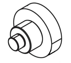
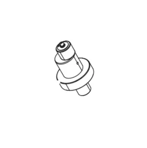
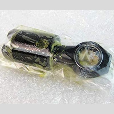
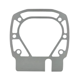

Output gear, crankshaft, slider, thrust washers, gasket and pump housing.
Fluid section assembly, fluid section screw, front cover and transducer.
Piston rod and pump manifold that hang from the slider's T-slot.
Not sure which 2850 drive part you need?
Call (713) 931-0006 with your PowrLiner 2850 serial number and we will match the gear, slider or thrust washer to its callout before you order.
(713) 931-0006Order by Parts Diagram