
The Impact 1040 service manual swaps the whole fluid section in four steps: remove the two nuts and washers under the sprayer and the fluid section retainer, slide the old section forward off the gear housing, set the new one in the clamp with the piston rod top in the slider's T-slot, then refit the block, washers and nuts and torque them to 100-130 in-lbs. The complete assembly is 0552603A. Relieve pressure and unplug first.
Most pump work on an Impact 1040 happens on the bench. This job is meant for the job site: Titan's 1040 service manual says the fluid section was designed to be easily replaced by another entire fluid section assembly for on-site replacement, and the procedure on page 11 is only four steps long. The swap itself is quick. The real work is deciding whether a whole assembly is the right fix and handling what is connected to it.
When a Complete Fluid Section Swap Makes Sense on a 1040
Symptoms that point to the fluid section
- Paint at the upper end of the fluid section, which the 1040 table ties to a worn upper packing or piston rod.
- Pressure that will not build or hold even with a good tip, clean filters and a tight suction set, traced in the table to leakage inside the fluid section or to worn valve seats.
- A sprayer that has to keep working on the job: on-site replacement is what Titan designed the assembly for.
Valve service, repack or the whole assembly
Three ways the 1040 manual restores the pump
| Route | What the manual does | Parts |
|---|---|---|
| Valve service | Cleans the foot valve and outlet valve and reverses or replaces damaged seats, worn balls or cages; the piston rod stays attached to the pump | Seats, balls and cages from the fluid section page |
| Repack | Unclamps the section, pulls the rod and fits new upper and lower packings before re-clamping | Repacking kit 0558740 |
| Complete swap | Unclamps the old section and clamps a complete assembly in its place | Fluid section assembly 0552603A |
The troubleshooting table sends worn seats to the valve service and a worn upper packing or rod to a repack; the complete assembly is the manual's on-site alternative. Our Impact 1040 parts guide shows what wears inside.
Rule out the cheaper causes first
A new pump will not cure a worn tip or a plugged screen. Before you order one, check the table's outside-the-pump causes: tip size and wear, the knob setting, the pump filter, gun filter and inlet screen, material escaping to the return hose with PRIME/SPRAY on SPRAY, a siphon tube air leak and leaking fittings. The 1040 filter assembly article covers the manifold filter.
Impact 1040 Fluid Section Parts and Tools
The complete assembly and the alternatives
Tools and supplies
- A wrench for the two nuts under the sprayer and a torque wrench that reads 100-130 in-lbs.
- A wrench for the high-pressure hose at the nipple.
- PTFE tape for the down tube/siphon tube adapter threads.
- The manual's general tool list for anything else: screwdrivers, needle nose pliers, an adjustable wrench, a rubber mallet and hex wrenches.
Pressure Relief and Unplugging Before the Swap
The 1040 manual's fluid section pages open with a warning box: follow the Pressure Relief Procedure from page 6, observe the other warnings about injection injury, moving parts and electric shock, and always unplug the sprayer before servicing. A swap disconnects the high-pressure hose from the pump, so the hose must be bled by triggering the grounded gun into a metal container, with the PRIME/SPRAY valve then moved down to PRIME. The whole sequence is in our Impact pressure relief article.
Replacing the 1040 Fluid Section: Step by Step
Steps 2 to 5 are the manual's four. The swap section does not mention the hoses, but the same manual's repack reassembly reconnects the high-pressure hose, the siphon tube and the return hose and refits the front cover, so Steps 1 and 6 deal with those.
Step 1: Relieve pressure, unplug and disconnect the hoses
With pressure relieved and the cord unplugged, take off the front cover, lift the return hose out of its clamp on the siphon tube, unscrew the siphon tube/siphon set from the foot valve, and loosen the high-pressure hose from the nipple on the back of the upper housing.
Step 2: Unclamp the fluid section
Under the sprayer, remove the two nuts and their washers, then take off the fluid section retainer. That releases the entire fluid section from its clamp.
Step 3: Slide the old section out
Slide the fluid section forward and off the gear housing. Set it aside for a valve service or repack later.
Step 4: Seat the new section in the T-slot
Place the new fluid section in the clamp on the gear housing, guiding the top of its piston rod into the T-slot on the slider assembly as it goes in. The manual singles this out, so check it before the clamp goes back on.
Step 5: Refit the block and torque the nuts
Lay the fluid section block back over the fluid section, refit the washers and nuts that secure it to the gear housing, and torque the nuts to 100-130 in-lbs.
Step 6: Reconnect, check the hose and prime
Attach the high-pressure hose to the nipple and tighten it with a wrench, without kinking it; if it touches the cart frame, turn the upper housing until it clears with the nipple within 45 degrees of the back of the unit. Tape the siphon tube adapter threads, fit the siphon tube/siphon set, clip the return hose in, refit the front cover and start the sprayer per the Operation section.
Test the 1040 After the Swap
Check for leaks
With the sprayer running, look at the hose connection at the nipple, the siphon tube joint at the foot valve and the top of the new fluid section. Relieve pressure and unplug before you tighten anything.
Confirm pressure and spray pattern
Titan's service notes ask you to test a repair before regular use and, if the sprayer still is not right, to review the procedure and the troubleshooting table. Bring the pressure up with the knob and spray a test pattern. If pressure is still poor, the remaining causes sit outside the fluid section: tip, filters, PRIME/SPRAY valve and suction leaks.
Fluid Section Swap Mistakes to Avoid
- Unclamping before the pressure is relieved and the cord is out.
- Sliding the new section in without the rod top engaged in the T-slot.
- Setting the torque wrench in the wrong unit: the clamp nuts take 100-130 in-lbs.
- Kinking the high-pressure hose, or leaving it resting on the cart frame.
- Skipping the PTFE tape on the siphon tube adapter, which invites the suction-side air leak the table warns about.
- Ordering the wrong assembly: the 1040T main assembly page shows a different fluid section, 0532437A.
Order the Impact 1040 Fluid Section
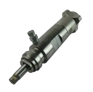
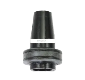
The complete 0552603A fluid section assembly is on the Titan Impact 1040 main assembly page, and its own fluid section diagram breaks it down. To rebuild instead, use the 0558740 repacking kit with the Impact 1040 packing guide; valve parts such as the 0294516 outlet valve seat and 00310 inlet seat are on the same diagram. A 1040T owner should start with Impact 1040T vs 1040. More procedures are under all repair guides.
Fluid section parts for the Impact 1040:

 −8%
−8%
Fluid section assembly 0552603A (callout 35) on the complete sprayer.
Every part inside the assembly, plus kit 0558740.
The slider assembly and gear housing the fluid section clamps to.
For 1040T owners: fluid section 0532437A.
Not sure 0552603A fits your sprayer?
Call (713) 931-0006 with the model and serial number, especially if it might be a 1040T, or check the 1040 main assembly diagram.
(713) 931-0006Order by Parts Diagram