
To reach an Impact 640's motor or gears, relieve pressure and unplug, remove the motor cover, belly pan and control panel screws, and disconnect the potentiometer, transducer and control panel board wires. Take out the four motor mounting screws and pull the motor. Inspect the armature gear, the 2nd stage gear 704-176 and the gear and crank assembly 704-173A, then reassemble with the thrust washer in place and five ounces of Lubriplate 314-171 in the gear box.
- When the Impact 640 Motor or Gears Need Replacing
- Impact 640 Motor and Gear Parts and Tools
- Before You Start: Pressure Relief, Power and Wiring
- Replacing the Impact 640 Motor or Gears: Step by Step
- Test the Impact 640 After the Drive Repair
- Motor and Gear Mistakes to Avoid
- Order Impact 640 Motor and Gear Parts
Titan's Impact 640 service manual (pages 7 and 8) prints the motor and gear procedures as one strip-down with two endings. The steps that take the covers, wiring and motor off are the same in both; after that you either fit a new motor or inspect and renew the gears behind it. The 740, 840 and 1040 manuals add a motor shroud, motor controller and motor baffle to the strip-down, so this sequence is for the 640 only.
When the Impact 640 Motor or Gears Need Replacing
Symptoms that point to the drive
- The motor powers but fails to rotate. The 640 troubleshooting table lists this under a unit that will not build or hold pressure.
- On models with the Digi-Trac display, a screen that names the drive: CHECK MOTOR (motor or motor hall effect sensors defective), BAD HALL CYCLE POWER (connection problems between motor and controller), HIGH MECHANICAL LOAD or HIGH MOTOR TEMPERATURE.
- Gear teeth that are damaged or badly worn when the motor comes out. The manual has you inspect the gears every time it does.
For each of those faults the troubleshooting pages recommend a Titan authorized service center. The maintenance section still prints both procedures, and they are what this guide follows, so be honest with yourself about the wiring work involved.
Rule out the cheaper causes first
Most no-run complaints in the 640 table are not the motor: the unit is not plugged in, a breaker has tripped, the pressure knob sits at minimum (which supplies no power), wiring is faulty or loose, the motor is too hot and needs to cool, or the ON/OFF switch is defective. A LOW VOLTAGE screen points to the power supply. For a unit that runs but makes no pressure, our Impact 640 won't prime or build pressure checklist covers the pump-side causes.
Impact 640 Motor and Gear Parts and Tools
Drive parts on the Impact 640 diagrams
The motor itself is not listed as a product on the 640 drive assembly page, and the armature gear comes with it: the manual replaces the entire motor if that gear is completely worn out. Call (713) 931-0006 with the model and serial number to confirm the motor. Our Impact 640 drive assembly article walks through what that page holds.
Tools and supplies
- The 640 manual's general tool list: Phillips and flat-blade screwdrivers, needle nose pliers, an adjustable wrench, a rubber mallet and hex wrenches from 3/8” down to 5/64”. The procedures do not assign a tool to each screw.
- The rubber mallet in particular, in case the motor will not come free.
- Lubriplate 314-171 for the gear box refill.
- The electrical schematic in the Parts List section of the manual, for every reconnection.
Before You Start: Pressure Relief, Power and Wiring
Both procedures begin by performing the Pressure Relief Procedure and unplugging the sprayer. On the 640 it is on page 6: trigger lock on, switch OFF, knob counterclockwise into the black-zone OFF position, lock released, the grounded gun triggered into a metal container to bleed the hose, lock back on, PRIME/SPRAY down to PRIME. Our Impact series pressure relief article explains why the motor switch alone is not enough.
Replacing the Impact 640 Motor or Gears: Step by Step
Steps 1 to 4 are shared by both procedures. Step 5 is the motor ending, Step 6 the gear ending, and Steps 7 and 8 put the sprayer back together.
Step 1: Relieve pressure, unplug and remove the motor cover
After the Pressure Relief Procedure, unplug the sprayer. Undo the two motor cover screws and lift off the cover; on I and IA models, disconnect the wires attached to the control board on the underside of the motor cover/enclosure assembly.
Step 2: Drop the belly pan and disconnect the motor wiring
Remove the three belly pan screws and the belly pan. At the back of the motor, disconnect the wire from the potentiometer, the wire from the transducer and the two wires from the control panel board.
Step 3: Free the control panel
Take out the four control panel mounting screws and pull the panel back to reach the control panel board, then disconnect the two wires coming from the motor.
Step 4: Pull the motor
Remove the four motor mounting screws and draw the motor out of the pump housing. If it will not dislodge, take off the front cover plate and carefully tap the front of the motor crankshaft, where it extends through the slider assembly, with a rubber mallet.
Step 5: Motor job: check the gears and fit the new motor
With the old motor out, inspect the gears in the pump housing for damage or excessive wear and replace any that need it. Install the new motor into the pump housing and secure it with the four motor mounting screws.
Step 6: Gear job: inspect the armature gear, 2nd stage gear and crank
Check the armature gear on the end of the motor; if it is completely worn out, the whole motor is replaced. Remove and inspect the 2nd stage gear, then the gear and crank assembly, and replace either one if damaged or excessively worn.
Step 7: Refit with the thrust washer in place
After gear work, reverse the strip-down with the thrust washer confirmed in place, and refill the gear box in the pump housing with five ounces of Lubriplate (314-171) as the manual's note directs. For either job, reconnect the potentiometer, transducer, control panel board and motor wires following the electrical schematic.
Step 8: Close up the 640
Position the control panel on the pump housing and fit its four mounting screws, then the belly pan with its three screws. On I and IA models, reconnect the control board wires on the underside of the motor cover/enclosure assembly; slide the motor cover over the motor and secure it with its two screws.
Test the Impact 640 After the Drive Repair
First power-up
Titan's general notes say to test a repair before regular operation and, if the sprayer does not operate properly, to review the repair procedure and then the troubleshooting charts. Plug in, start the sprayer by the Operation section, and watch the display if your model has Digi-Trac. CHECK TRANSDUCER, CHECK POTENTIOMETER and BAD HALL CYCLE POWER all appear when a connection is missing or poor, so if one shows after this job, unplug and check the wiring you disturbed first.
Pressure check
Turn the knob clockwise from minimum; the manual says this supplies power and raises the pressure setting. If the motor runs but pressure will not build, the table's remaining causes are on the pump side: tip, filters, PRIME/SPRAY valve, suction leaks, packings and valves.
Motor and Gear Mistakes to Avoid
- Disconnecting by pulling the wire rather than the connector.
- Losing track of the potentiometer, transducer, control panel board and motor wires; reconnect from the schematic.
- Forcing a stuck motor. The manual's method is a careful tap with a rubber mallet on the front of the crankshaft, with the front cover plate off.
- Leaving the thrust washer out on reassembly.
- Skipping the five ounces of Lubriplate after gear work.
- Fitting new gears to a motor whose armature gear is completely worn; the manual replaces the motor in that case.
Order Impact 640 Motor and Gear Parts
The Impact 640 drive assembly page carries the 704-176 2nd stage gear, the 704-173A crankshaft/gear assembly and the 704-174 thrust washer; the gear box refill is Lubriplate 314-171. The covers, belly pan, control panel and potentiometer are on the main assembly page. On a 640I or 640IA, what IntelliSync and ActivGuard add explains the extra control board wiring. If the pump end needs work too, follow the Impact 440 and 640 packing guide, or see all repair guides.
Drive parts for the Impact 640:




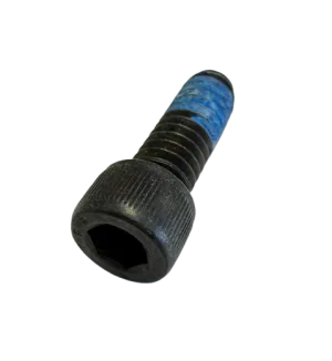
2nd stage gear, crankshaft/gear assembly, thrust washer, slider and motor hardware.
Motor cover, belly pan, control panel, potentiometer and transducer jumper.
Not sure which gear or motor fits your 640?
Call (713) 931-0006 with the model and serial number, or open the Impact 640 drive assembly diagram and match the callout.
(713) 931-0006Order by Parts Diagram