Titan 0277937 Turbine Assembly
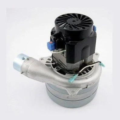
The Titan 0277937 Turbine Assembly is a three-stage, 120-volt replacement assembly designed for the Titan CAPSpray CS8100 HVLP spray system, helping restore the airflow required for controlled coating atomization and professional finishing performance.
| Detail | Verified Information |
|---|---|
| Brand | Titan / CAPSpray |
| Compatible machine | CAPSpray CS8100 Spray System, model 0277030 |
| Part number | 0277937 |
| Configuration | Three-stage, 120V turbine assembly |
| System location | Internal turbine and airflow section |
Restore Reliable Airflow in Your CAPSpray CS8100 System
The Titan 0277937 is the three-stage, 120-volt turbine assembly used within the CAPSpray CS8100 HVLP spray system. It is the central powered component responsible for producing the air delivered through the turbine hose to the spray gun.
Product Overview
A turbine is the airflow source in a turbine-powered HVLP spraying system. Instead of relying on a separate shop compressor, the CS8100 uses its internal electric turbine to supply a high volume of air at relatively low pressure. That moving air travels through the connected hose to the spray gun, where it supports coating atomization and transfer to the work surface.
When the original turbine has sustained electrical wear, brush deterioration, commutator damage or heat-related failure, the system may stop producing the airflow needed for normal spraying. Replacing the failed assembly can restore the powered air-delivery section without replacing unrelated housings, filters, controls or external accessories that remain serviceable.
This component should be selected by exact part number and machine identification. Similar-looking turbine motors may differ in voltage, number of stages, mounting arrangement or electrical connections. The verified specification for this component is three-stage and 120 volts.
| Product overview | Internal electric turbine and airflow-generating assembly |
|---|---|
| Primary function | Produces the air supplied to the HVLP spray gun |
| Verified machine | CAPSpray CS8100 Spray System, model number 0277030 |
| Electrical configuration | 120 volts |
| Turbine configuration | Three-stage |
| Assembly position | Item 29 in the CS8100 turbine housing parts diagram |
| Typical service reason | Turbine failure, damaged commutator, excessive arcing or loss of powered airflow |
How the Turbine Supports HVLP Spraying
In the CS8100 system, the turbine supplies the air used by the connected spray gun. A correctly operating turbine helps the gun break the coating stream into a controlled spray pattern. The final finish also depends on material viscosity, gun setup, airflow adjustment, fluid delivery and operator technique, but the turbine must first provide sufficient air through the hose.
The system incorporates separate paths for atomizing air and turbine cooling air. The atomizing-air filter helps prevent contaminating particles from reaching the finish, while the cooling-air filter supports ventilation through the turbine housing. This makes filter condition directly relevant to turbine temperature and service life.
A clogged filter can restrict circulation, raise operating temperature and place unnecessary stress on the motor. Replacing a damaged turbine without correcting restricted filters may allow the underlying heat problem to continue. Inspecting and servicing the complete airflow path is therefore an important part of a professional repair.
Common Symptoms That Require Inspection
Do not assume that every airflow complaint requires immediate turbine replacement. Begin with basic system inspection and isolate the cause before ordering electrical components.
- Restricted airflow: inspect the spray-gun airflow setting, hose path and both turbine filters.
- Filter warning light illuminated: clean or replace the filters and confirm unobstructed airflow.
- No turbine power: verify the grounded power supply, cord condition, switch and fuse before condemning the motor.
- Excessive arcing or sparking: worn brushes or a damaged commutator may require authorized service or turbine replacement.
- Unusual heat or odor: disconnect the equipment and inspect the cooling-air path before continued use.
- Unstable air delivery: inspect filters, hose connections and internal components for restriction, looseness or damage.
Installation and Service Guidance
Turbine replacement involves a 120-volt electrical assembly and internal machine components. Disconnect the power cord before opening the housing or beginning service. Allow heated fittings and internal parts to cool, and use a qualified technician when electrical diagnosis or internal motor replacement is outside the operator’s normal service capability.
- Confirm that the machine identification matches the CS8100 model and that the existing component carries the correct part reference.
- Disconnect the system from the grounded electrical supply and prevent accidental reconnection.
- Record wire routing, hose routing, fastener locations and the orientation of surrounding components before removal.
- Inspect the filter cans, screens, foam pieces, silencer components and cooling passages for contamination or deterioration.
- Check the exhaust-hose fitting and hose for cracks, looseness or heat damage before reassembly.
- Secure all electrical connections and mechanical fasteners according to the correct service procedure.
- After reassembly, test the unit in a safe, ventilated area and verify normal airflow before beginning coating work.
Never operate the turbine with missing filters or obstructed cooling passages. Do not modify the supplied grounding system, substitute an incompatible voltage configuration or bypass protective electrical components.
Maintenance That Helps Protect the Replacement
Regular airflow-system maintenance is one of the most important ways to protect the turbine. The CS8100 uses a fine two-stage atomizing-air filter and a coarser cooling-air filter. Remove contamination by gently tapping the filters or using suitable compressed air. Filters may also be cleaned with the approved method described for the machine, but they must be completely dry before reinstalling them.
The two-stage filter must be installed in its correct filter can with its green side facing the turbine. Incorrect placement, wet filtration media or heavily clogged filters can compromise airflow and increase heat inside the machine.
The maintenance schedule also calls for turbine-brush inspection by an authorized service center every 400 operating hours. Brush inspection is preventive service: worn brushes may contribute to power interruption, excessive arcing and commutator damage if allowed to continue operating.
| Service area | Recommended attention |
|---|---|
| Atomizing-air filter | Clean regularly; replace when cleaning no longer restores suitable condition. |
| Cooling-air filter | Keep free of dust and coating residue to prevent heat buildup. |
| Turbine brushes | Have wear checked by an authorized service center every 400 hours. |
| Air hose and fittings | Inspect for leaks, cuts, damaged couplings and restricted airflow. |
| Power cord and grounding | Inspect before operation and use only a properly grounded electrical supply. |
Related CS8100 Components
A turbine service project may reveal wear or contamination in nearby parts. The following components are identified in the same CS8100 airflow and housing assembly. They are listed for inspection and parts-identification purposes; they are not automatically included with the turbine.
| Part number | Component | Inspection reason |
|---|---|---|
| 0279937 | Filter replacement kit | Restricted or deteriorated filtration media |
| 0277918 | Turbine brush kit | Scheduled brush-wear inspection |
| 0277159 | Silencer assembly | Air-path condition and noise control |
| 0276511 | Exhaust-hose fitting | Secure turbine exhaust connection |
| 9881911 | Exhaust hose | Cracks, looseness or heat damage |
| 0275710 | 15-amp slow-blow fuse | No-power diagnosis and circuit protection |
| 0277472 | Airflow switch | Filter-warning system operation |
Commercial and Contractor Benefits
Replacing the failed internal assembly can extend the useful service life of an otherwise repairable CS8100 system. This can be particularly valuable for finish contractors, cabinet shops, furniture refinishers, equipment-maintenance departments and rental operations that already own compatible guns, hoses and accessories.
- Restores the primary powered airflow source after confirmed turbine failure.
- Allows service of the affected assembly without automatically replacing the complete spraying system.
- Supports continued use of compatible CS8100 housings and external equipment that remain in suitable condition.
- Helps reduce downtime caused by weak airflow, motor failure or internal electrical damage.
- Provides an exact part-number reference for more accurate repair planning and purchasing.
Buying Checklist
FAQ Section
Review these common questions before diagnosing or replacing the CS8100 turbine.
Which machine uses this turbine assembly?
Is this a 120-volt turbine?
Does weak airflow always mean the turbine has failed?
What can cause excessive sparking inside the turbine?
How often should the turbine brushes be inspected?
Why must the filters be maintained?
Is professional installation recommended?
No reviews yet. Be the first to review this product!